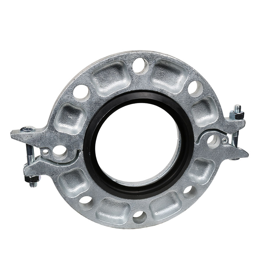
Gruvlok® 0390210227 FIG 7012 Pipe Flange With Grade E EPDM Gasket, 8 in, Galvanized, Ductile Iron, Grooved, Domestic
CBPN:84073
UPC:690291114847
MPN:0390210227
DESCRIPTION
Gruvlok® Pipe Flange, Series: FIG 7012, 8 in Nominal, 11-3/4 in Bolt Circle, 8 Bolt Holes, 7/8 in, Grooved, 8-5/8 in Outside Dia, 300 psi, -40 to 230 deg F, Ductile Iron, Galvanized, Domestic
The Gruvlok® Fig. 7012 Flange allows direct connection of Class 125 or Class 150 flanged components to a grooved piping system. The two interlocking halves of the 2 thru 12 in sizes of the Gruvlok® Flange are hinged for ease of handling, and are drawn together by a latch bolt, which eases assembly on the pipe. Precision machined bolt holes, key and mating surfaces assure concentricity and flatness to provide exact fit-up with flanged, lug, and wafer styles of pipe system equipment. A specially designed gasket provides a leak-tight seal on both the pipe and the mating flange face. The 14 thru 24 in sizes of the Gruvlok® Fig. 7012 Flange are cast in four segments. A sleek profile gasket design allows quick and easy assembly of the Gruvlok® Flange onto the pipe. All Gruvlok® Fig. 7012 Flanges have designed-in anti-rotation tines which bite into and grip the sides of the pipe grooves to provide a secure, rigid connection. The Gruvlok® Fig. 7012 Flange requires the use of a steel adapter insert when used against rubber faced surfaces, wafer/lug design valves and serrated or irregular sealing surfaces. In copper systems a phenolic adapter insert is required, in place of the steel adapter insert.
Gruvlok® 0390210227 FIG 7012 Pipe Flange With Grade E EPDM Gasket, 8 in, Galvanized, Ductile Iron, Grooved, Domestic
CBPN:84073
MPN:0390210227
UPC:690291114847
DESCRIPTION
Gruvlok® Pipe Flange, Series: FIG 7012, 8 in Nominal, 11-3/4 in Bolt Circle, 8 Bolt Holes, 7/8 in, Grooved, 8-5/8 in Outside Dia, 300 psi, -40 to 230 deg F, Ductile Iron, Galvanized, Domestic
The Gruvlok® Fig. 7012 Flange allows direct connection of Class 125 or Class 150 flanged components to a grooved piping system. The two interlocking halves of the 2 thru 12 in sizes of the Gruvlok® Flange are hinged for ease of handling, and are drawn together by a latch bolt, which eases assembly on the pipe. Precision machined bolt holes, key and mating surfaces assure concentricity and flatness to provide exact fit-up with flanged, lug, and wafer styles of pipe system equipment. A specially designed gasket provides a leak-tight seal on both the pipe and the mating flange face. The 14 thru 24 in sizes of the Gruvlok® Fig. 7012 Flange are cast in four segments. A sleek profile gasket design allows quick and easy assembly of the Gruvlok® Flange onto the pipe. All Gruvlok® Fig. 7012 Flanges have designed-in anti-rotation tines which bite into and grip the sides of the pipe grooves to provide a secure, rigid connection. The Gruvlok® Fig. 7012 Flange requires the use of a steel adapter insert when used against rubber faced surfaces, wafer/lug design valves and serrated or irregular sealing surfaces. In copper systems a phenolic adapter insert is required, in place of the steel adapter insert.
Specifications
Item Features
- Grooved pipe couplings and fittings are used to join pipes in both wet and dry systems.

